Skip to content

Solid-State Transformers

Next Generation Energy Infrastructure

An integrated medium-voltage-to-DC conversion platform for customer and partner pilots — 3 MW, 13.8 kVAC ↔ 800 VDC, bidirectional, with XPowerOS™ controls.

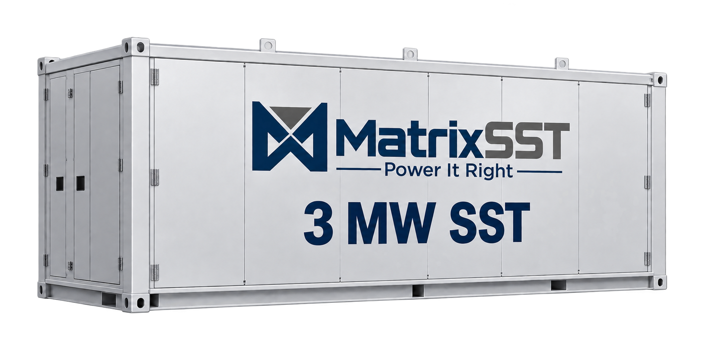
The MatrixSST 3 MW solid-state transformer: a containerised enclosure carrying the MatrixSST wordmark and a 3 MW SST label.

3.0 MW

Rated power

13.8 kVAC

Grid interface

800 VDC

Output voltage

98.5%

Highest efficiency target

Why SSTs now

DC-Native AI Power Infrastructure and Grid Modernization

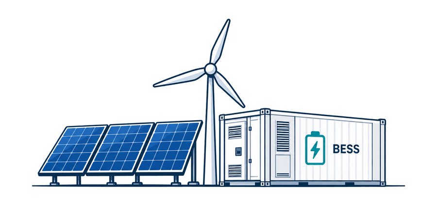
Solar panels, a wind turbine and a battery energy storage container.

Renewables + Storage for Grid

Solar and batteries are DC

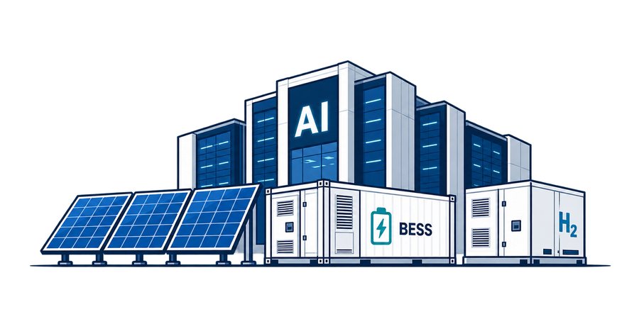
An AI data center building alongside solar panels, a battery storage container and a hydrogen unit.

Renewable Power for AI Data Centers

Moving toward 800 VDC

An electric van, a charging pedestal, an electric truck and an electric bus.

Fleet Charging Microgrids (DC Input)

Emerging high-power charging is DC

One SST platform connects the MV grid to multiple DC-native applications.

Bidirectional • Intelligent • Grid-interactive
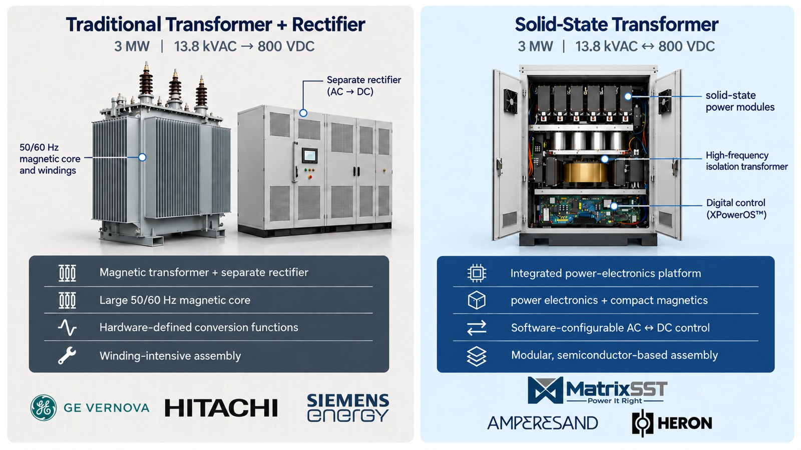
Distribution Transformers: From Coils to Power Electronics

A side-by-side comparison. Left: a traditional 3 MW 13.8 kVAC to 800 VDC arrangement of a magnetic transformer with a separate rectifier, described as hardware-defined and winding-intensive. Right: a solid-state transformer of the same rating, described as an integrated power-electronics platform with compact magnetics, software-configurable AC to DC control and modular semiconductor-based assembly.

Product

MatrixSST 3 MW Product Overview

An integrated medium-voltage-to-DC conversion platform for customer and partner pilots.

13.8 kVAC  ↔  800 VDCBidirectional power conversion

Initial Product

  • 3 MW design rating
  • 13.8 kVAC / 800 VDC bidirectional interface
  • Integrated conversion, isolation, and XPowerOS™ controls

Project Integration

  • Connects to site AC switchgear and DC protection
  • Coordinates with the site EMS
  • Resource converters, storage, and downstream equipment selected for the application

Development Status

  • Pre-sample development
  • First operational pilot trial targeted for Q1 2027
  • Pilot scope and supported functions agreed with each partner

Focused MV-to-DC conversion, with project interfaces defined collaboratively.

MatrixSST 3 MW Product Specification

Preliminary design targets

Output

Rated power
3.0 MW
Rated current
3,750 A
Overload
110% for 10 min
Output voltage
800 VDC
Voltage accuracy
−0.5% to +0.5% at steady state
Highest efficiency
98.5%

Input

Phases
3
Frequency
45–65 Hz
Voltage
10–13.8 kVAC (line-to-line)
Voltage range
−10% to +10%
Current THD
<3% above 50% load
Power factor
>0.98 in load operation mode,
−0.9 to 0.9 in reactive mode

Communication & Protection

Communication
CANRS485EthernetIEC 103/104IEC 61850Modbus RTUModbus TCP/IP
Operating modes
Voltage source modeCurrent source modeSTATCOM mode (planned)
Protection
OvercurrentOvervoltageUndervoltageShort circuitOvertemperature
LCD display
Input voltage, output voltage, input current, output current, module running / fault status, overall running status

Environment & Mechanical

Operating location
Indoors
Operating temperature
−4 to +105 °F
Altitude
≤6,560 ft
Storage temperature
−40 to +150 °F
Cooling
Forced air
Enclosure protection
IP30
Planned certifications
UL 1741UL 2877UL 1562

Applications

Four ways one 13.8 kVAC ↔ 800 VDC platform gets used.

Application I

Renewables + Storage for the Grid

An integrated MV-to-DC interface for renewable generation and storage.
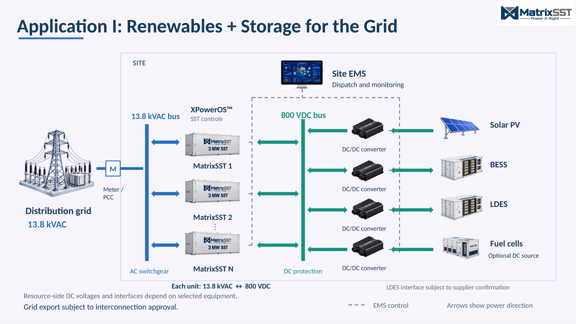
Application I single-line diagram: distribution grid at 13.8 kVAC through meter/PCC and AC switchgear to MatrixSST units 1 to N, feeding an 800 VDC bus that connects solar PV, BESS, LDES and optional fuel cells through DC/DC converters, under site EMS and XPowerOS control.

Value proposition

Integrated 13.8 kVAC ↔ 800 VDC conversion and XPowerOS controls
Simplifies procurement and engineering by consolidating transformer, converter, and local-control functions into one platform, reducing separate equipment interfaces and interconnecting cabling.
Shared DC bus for solar and storage
Supports solar-to-storage energy transfer through appropriate DC/DC interfaces without routing through the AC grid.
Bidirectional power control coordinated with the site EMS
Supports grid charging, controlled export, and storage dispatch. Enables on-site energy use where local loads are present.
Oil-free conversion and isolation
Eliminates transformer insulating oil and the associated leak inspections, seal repairs, and spill-management burden compared with oil-filled transformer systems.
Modular 3 MW units
Provides a path to expand conversion capacity as generation and storage capacity grow.
Built-in STATCOM capability
Adds reactive-power and voltage support to help address project-specific grid requirements.

Focused MV-to-DC conversion, with storage and resource interfaces selected to fit each project.

Application II

Renewable Power for AI Data Centers

Integrate grid power and on-site energy resources into a scalable DC campus architecture.
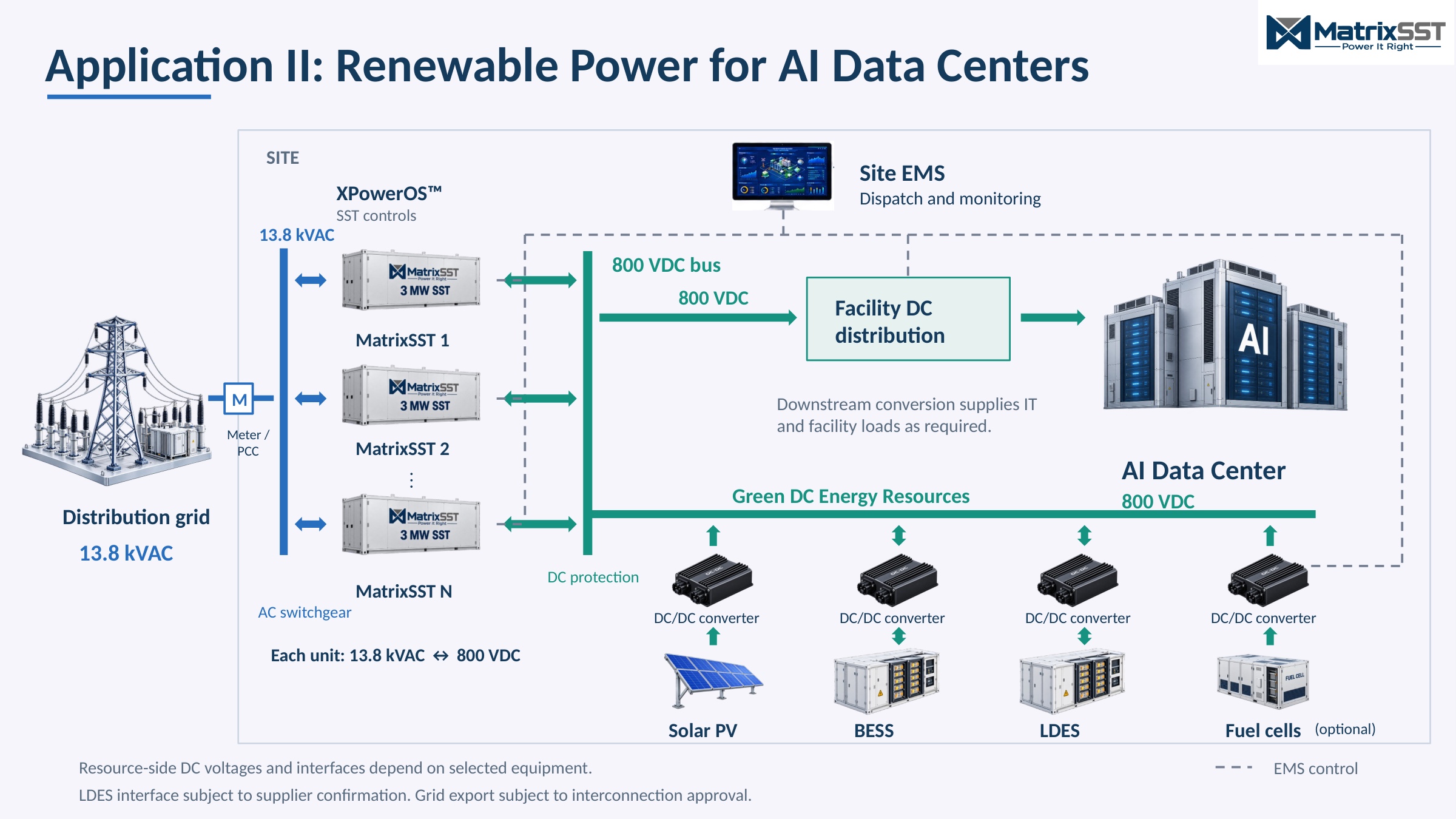
Application II single-line diagram: distribution grid at 13.8 kVAC to MatrixSST units 1 to N, feeding an 800 VDC bus that supplies facility DC distribution for an AI data center, and a green DC energy resources bus for solar PV, BESS, LDES and optional fuel cells through DC/DC converters.

Value proposition

Integrated MV-to-DC conversion and XPowerOS controls
Simplifies procurement and engineering by consolidating transformer, converter, and local-control functions into one platform, reducing separate equipment interfaces and interconnecting cabling.
800 VDC site interface
Aligns with emerging DC data center architectures, with downstream conversion matched to facility requirements.
Shared DC architecture for renewables, storage, and optional fuel cells
Enables compatible on-site resources to serve campus demand alongside grid power.
Bidirectional power control coordinated with the site EMS
Supports management of grid import, storage charging, and permitted export as campus demand changes.
Oil-free conversion and isolation
Eliminates transformer insulating oil and the associated leak inspections, seal repairs, and spill-management burden compared with oil-filled transformer systems.
Modular 3 MW units
Provides a path to expand conversion capacity alongside phased data center deployment.

Focused MV-to-DC conversion, with storage and resource interfaces selected to fit each project.

Application III

Fleet DC Fast Charging Microgrids

Share DC power infrastructure across truck, bus, and commercial-van charging.
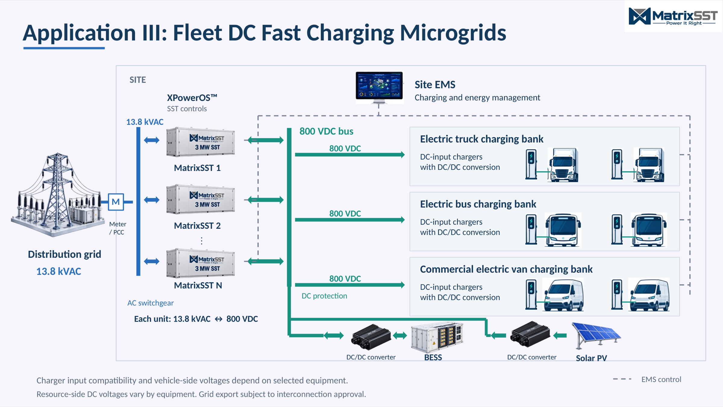
Application III single-line diagram: distribution grid at 13.8 kVAC to MatrixSST units 1 to N, feeding an 800 VDC bus that serves electric truck, electric bus and commercial electric van charging banks, with BESS and solar PV connected through DC/DC converters.

Value proposition

Integrated 13.8 kVAC-to-800 VDC conversion and XPowerOS controls
Simplifies procurement and engineering by consolidating transformer, converter, and local-control functions into one platform, reducing separate equipment interfaces and interconnecting cabling.
Common DC bus serving multiple charger banks
Allows truck, bus, and van charging banks to share upstream conversion capacity through compatible charger-specific DC/DC interfaces.
Solar and BESS integration
Enables on-site solar use and storage-assisted peak demand management, subject to system sizing and dispatch.
XPowerOS coordinated with site energy and charging management
Supports allocation of available power across charger banks to meet fleet schedules within site power limits.
Oil-free conversion and isolation
Eliminates transformer insulating oil and the associated leak inspections, seal repairs, and spill-management burden compared with oil-filled transformer systems.
Modular 3 MW units
Provides a path to add conversion capacity as vehicles and charging infrastructure are deployed.

Focused MV-to-DC conversion, with storage and resource interfaces selected to fit each project.

Application IV

Bridging Utility Power Grids

Balance loading across nearby distribution networks to make better use of existing capacity.
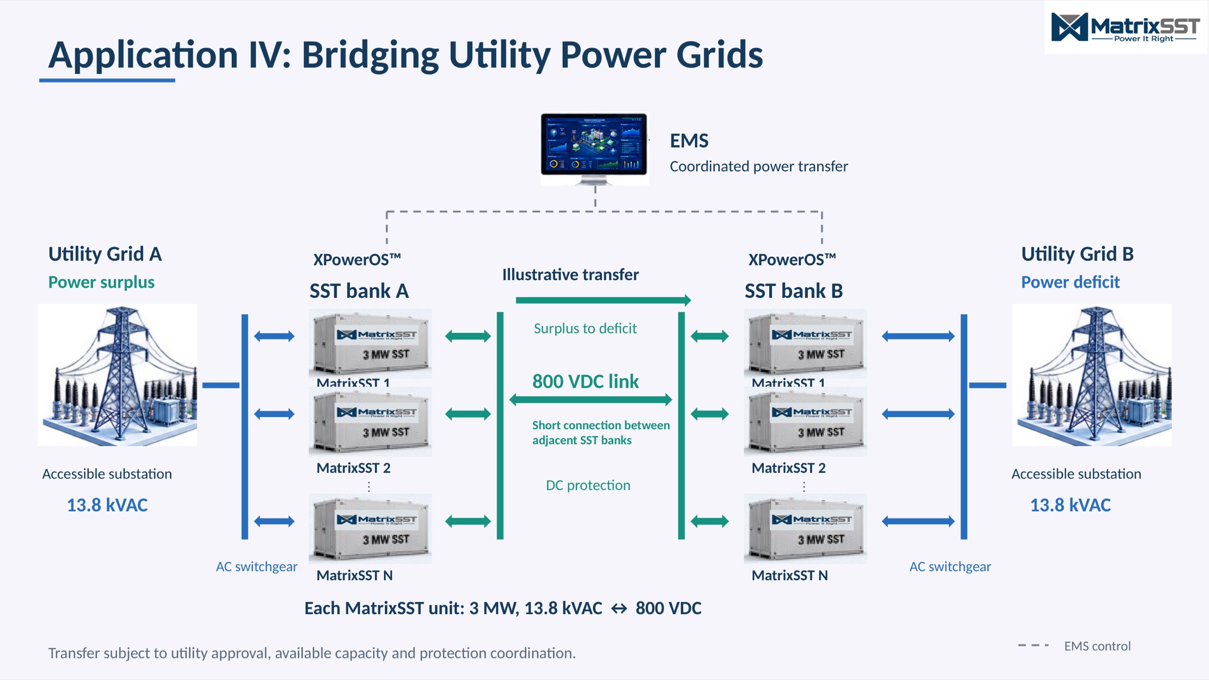
Application IV single-line diagram: Utility Grid A with a power surplus and Utility Grid B with a power deficit, each at 13.8 kVAC, connected through SST banks A and B joined by a short 800 VDC link, coordinated by an EMS.

Value proposition

Controlled bidirectional transfer between local grids
Shares available power with a neighboring network facing higher demand, potentially deferring selected capacity upgrades.
DC-linked interconnection between adjacent SST banks
Enables controlled power exchange without directly paralleling the two AC networks.
XPowerOS coordinated with the EMS
Adjusts transfer direction and magnitude as network conditions change, within utility-defined operating limits.
Integrated 13.8 kVAC ↔ 800 VDC conversion and local controls
Simplifies procurement and engineering by consolidating transformer, converter, and local-control functions into one platform, reducing separate equipment interfaces and interconnecting cabling.
Modular 3 MW units in paired SST banks
Provides a path to expand transfer capacity as local demand and available network capacity grow.
Oil-free conversion and isolation
Eliminates transformer insulating oil and the associated leak inspections, seal repairs, and spill-management burden compared with oil-filled transformer systems.

Focused MV-to-DC conversion for controlled grid-to-grid power sharing and better use of existing infrastructure.

Platform

MatrixSST's End-To-End Technology Platform

U.S. Controlled IP

MatrixSST-developed • Owned • Controlled

XPowerOS™

Control • Protection • Orchestration

Integrated SST Architecture

Cost-optimized • Manufacturable

Commercially available, mass-produced components

Modular Product Platform

3 MW first → Broader MV variants

Proven MV Engineering Team

6–35 kV and 1–20 MW designs

Highly experienced MV team

MatrixSST: One Integrated, Intelligent Power Platform

Feature-by-feature comparison of a traditional distribution transformer system against MatrixSST product targets.
FeatureTraditional Distribution Transformer System*MatrixSST Product Targets
IntegrationSeparate transformer, power electronics and controlsIntegrated conversion, isolation, and controls
Conversion13.8 kVAC → 600–690 VAC → 800 VDC (external rectifier / PCS)Integrated 13.8 kVAC ↔ 800 VDC
Power Rating~3.15 MVA transformer / ~3 MW DC system output3.0 MW DC output
Software PlatformSeparate vendor controls and integrationXPowerOS: Software-defined bidirectional power control
Grid CapabilitiesExternal equipment for grid supportIntegrated grid-forming, voltage and frequency control
Control ResponseResponse depends on PCS/controllerSub-millisecond spike detection/control (planned)
Highest Efficiency~96.5 – 98.0% estimated98.5% target
Lead-Time12 – 24+ months3 – 6 months target when available to order

Fewer components • Shorter equipment lead time targeted • Integrated power controls

*Legacy reference: ~3.15 MVA transformer plus bidirectional PCS/rectifier, controls, protection, cooling and switchgear/ATS to convert 13.8 kVAC to regulated 800 VDC. Schneider Trihal and Prolec GE.

Proven Medium-Voltage Power-Electronics Track Record

  • 30

    experienced MV hardware engineers (10 full-time, 20 contractors)

  • 15+ years

    experience among key engineers

  • 6–35 kV · 1–20 MW

    systems designed, spanning conversion, controls, thermal design, packaging and testing

Example systems the team previously built
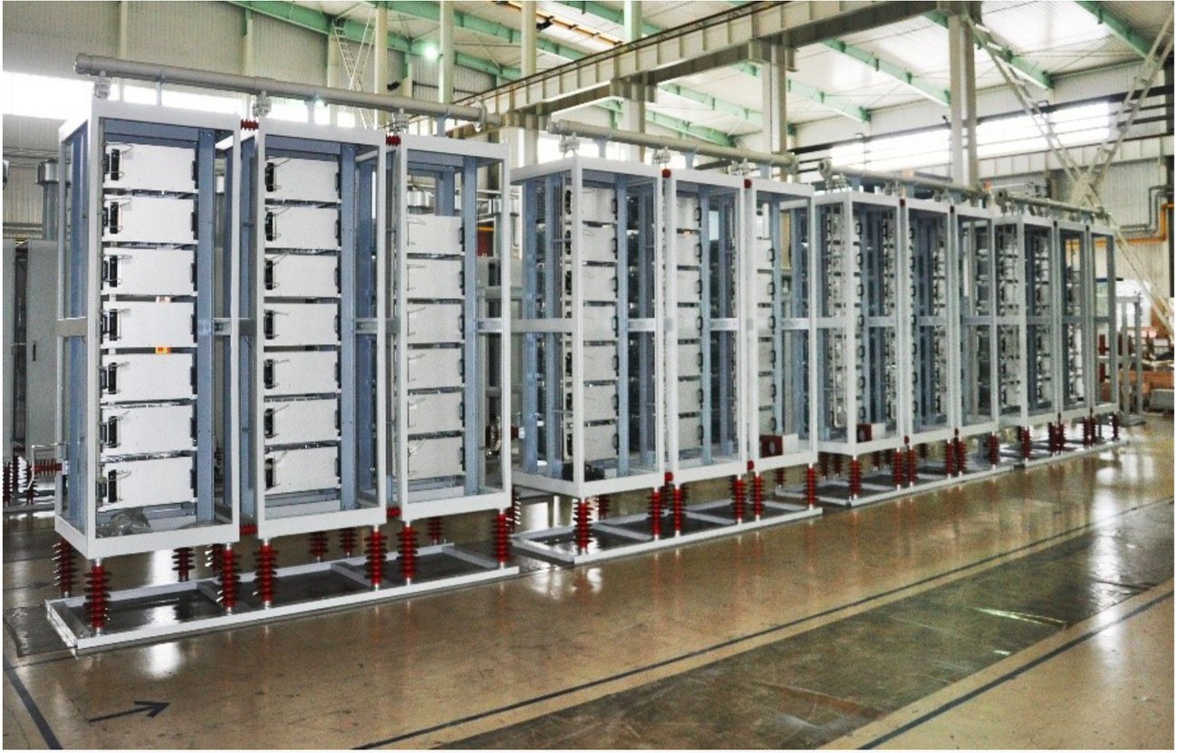
A row of tall medium-voltage converter cabinets standing on insulators in an assembly hall.
1–10 MW 10 kV Liquid-Cooled
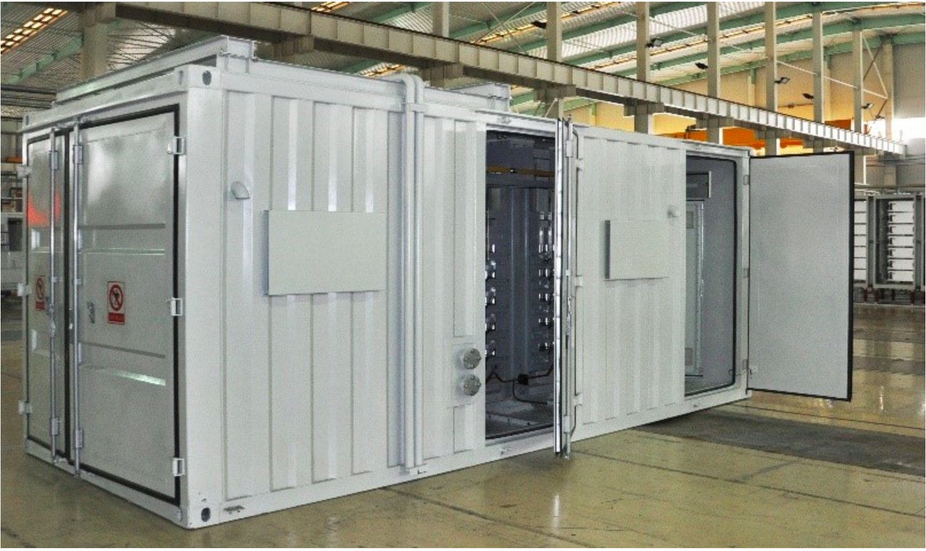
A containerised medium-voltage power-electronics system with its access doors open.
7–20 MW 35 kV Air-Cooled

Proven MV experience de-risks SST development and commercialization.

Roadmap

MatrixSST Commercialization Roadmap

Target development and deployment milestones.

  1. 2026

    Build

    3 MW prototype + core capability demonstration

  2. Q1 2027

    3 MW Operational Pilot

    Integrated 3 MW hardware + XPowerOS™

  3. Q2–Q4 2027

    Qualify + Customer Pilots

    Certification, reliability testing + customer validation

  4. Q4 2027

    Initial Scale

    Qualified product + initial customer shipments

Leading in SST Commercialization

A validated but still-emerging SST category creates room for differentiated commercial execution.

High Growth MV Markets

  • Renewables + storage for the Grid
  • Renewable power for AI Data Centers
  • Fleet charging microgrids (DC input)

Proven MV Execution

6–35 kV / 1–20 MW experience

Time-To-Market Ready

Field trial operational pilot Q1CY27

Capital-Efficient Model

Existing team + outsourced production

Pilots

MatrixSST Pilot Projects for Customers & Partners

Work directly with our product and engineering leadership to define and validate your pilot.

Customers & Partners

  • Renewable energy, storage, and fuel-cell equipment suppliers
  • Utilities, IPPs, and microgrid developers/operators
  • Data center and fleet-charging developers/operators

Pilot Objectives

  • Operate equipment and verify agreed performance and integration criteria
  • Share operating data to assess results and improve the product
  • Coordinate site access, utility engagement, and required approvals
  • Host periodic demonstrations by mutual agreement

Commercial Approach & Early-Partner Benefits

  • Early access to the MatrixSST 3 MW SST
  • Paid pilots with early-collaboration discounts
  • Agreed scope, responsibilities, schedule, and data-sharing terms
  • Defined path to follow-on deployments, contingent on pilot results

Pilot Selection & Next Steps

Identify a suitable site, confirm technical fit, and jointly define the pilot.

  1. 1

    Identify a Candidate Site

    • Application suited to the 3 MW platform and its 13.8 kVAC / 800 VDC interfaces
    • Named technical sponsor and access to site engineering
    • Willingness to support operating-data collection and agreed demonstrations
  2. 2

    Share Initial Project Information

    • Application, location, and target deployment timing
    • Available single-line diagram and AC/DC voltage requirements
    • Expected power profile, connected equipment, and import/export needs
  3. 3

    Define the Pilot Together

    • Review technical fit and integration requirements
    • Assign engineering responsibilities and a lead for utility engagement
    • Agree on success criteria, approval steps, schedule, and commercial terms

Next step: Schedule a joint technical scoping meeting.

Preliminary information is sufficient to begin.

Contact

Schedule a joint technical scoping meeting.

Preliminary information is sufficient to begin. Tell us the application, the site and the timing, and we will review technical fit with you.

  • The 3 MW platform interfaces at 13.8 kVAC and 800 VDC, bidirectionally.
  • First operational pilot trial is targeted for Q1 2027.
  • Pilot scope and supported functions are agreed with each partner.
MatrixSST Inc.
920 Hillview Ct., Suite 195
Milpitas, CA 95035
USA